6/5 - 6/8
- Cormac Lynch
- Jun 9, 2023
- 1 min read

This week I tried to fix my PCB by removing the solder from the pad, but there was too much and it got stuck on the board, so I had to cut one more. I had to redesign it with higher trace clearance so I could use the larger 1/32" bit which was much faster than the 1/64" bit.

On the actual PCB milling machine I used for the project I had to change the clearance on the machine as well, making it 4 millimeters. I did this in order to stop solder from accidentally getting on the pad as I soldered. This would have caused the pin to become connected to the entire board. I also tried to solder a little bit more carefully this time and not get solder all over the board like some of the other attempts

This is the top of the PCB with only the parts I needed in order to test one of the breakbeam sensors. I needed the metro mini, multiplexer, a three pin header, and a 2 pin header.
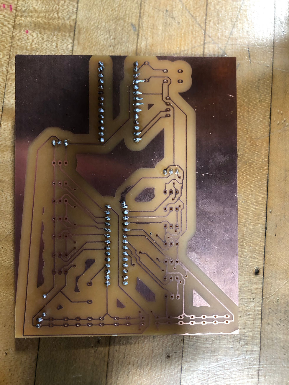
This is the bottom of the PCB, I tried to solder it neater than I had with the previous PCBs so it would actually work, so if I put too much solder on, I would spread it out.
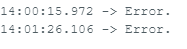
When I tested the code, the sensors weren't working, so I had to test what the problem was. In the code I added a line that tested if the multiplexer was starting and if it wasn't it would print "error" in the serial monitor. Next week I will have to try and fix the multiplexer, so it actually starts.


Comments